Volvo button hacking
The curious case of Volvo’s center console buttons
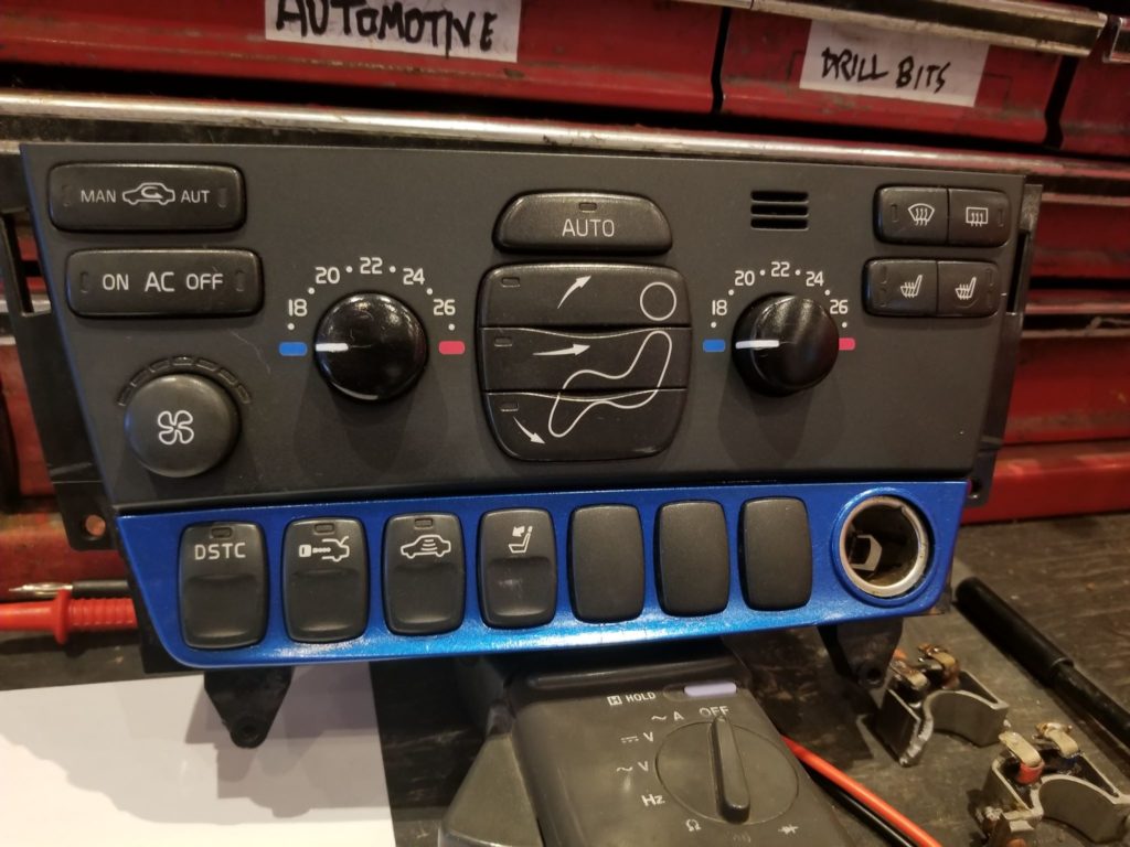
My S60R (like most P2 Volvos) has this row of buttons below the climate controls, in front of the shifter. Depending on the configuration of the car, these buttons can vary in number, position, and function. For example my buttons are, from left to right: traction control, valet trunk lock, microwave disabler, and headrest folder. Other cars have buttons for park assist, rear AC, folding mirrors, yaw control, window lock etc. My car doesn’t have those options, so I don’t have those buttons.
I took them apart for cleaning one day while repairing my radio and found myself stuck.. I couldn’t remember in which order the buttons went back in. Looking at the mainboard revealed no helpful information, and the buttons (apart from the picture on the front) were all identical. Oh well, worst case I have the wrong pictures on the wrong buttons. I put them back in and… they worked just fine. No way I’m that good.. I’m going to re-arrange the buttons and try again. They still worked. Okay wait a second, there are only 7 slots here, but there are more than 7 different buttons in existence, how does the car… hmmm… the buttons function must be programmed inside the button itself.
This car relies really heavily on the canbus, perhaps the mainboard is just a passthrough for the canbus, and the buttons have chips inside programmed with their functionality? It would make sense considering the buttons cost 60-80 bucks each, and they are connected to the mainboard with.. a 12-pin connector.. no way they need that many pins for canbus. Linbus? No, still way too many pins. This is a puzzler.
I opened up one of the buttons and was surprised to see there is no microcontroller inside. A simple board with a button, a lamp, an LED (some buttons dont have an LED), a couple diodes, and thats it. Maybe each button connects to a different set of pins and thats what determines the function? I opened up a different button and found the exact same circuit board, with the same components and the same board number. Something fishy is going on here.
I actually missed it at first, but every button has a different combination of diodes. I charted out every button I could find, and traced the various connections, and found that the presence of diodes 1 through 4 actually determine the buttons function (there are actually 5 diodes spots in each button, but diode 5 is always present because its part of the pushbutton circuit). The Climate Control Module keeps track of button presses and reports them to the Central Electric Module, which in turn reports back with whether or not the LEDs inside the buttons should be on or off. The placement of the buttons don’t matter at all, and the buttons function is really basically coded into the button module itself. Neat.
So because 4 simple diodes make up the button code, this means not only are there theoretically 16 different buttons in existence, but we can very easily convert an existing button to another function. HOWEVER, these cars are smart, and after poking around VIDA for a bit I learned that many functions are programmed in the Central Electric Module, and the Climate Control Module will check to see if a certain button is allowed to be used in the car. For example, if I install a Folding Mirror button in my car and I don’t have Folding Mirrors, the button will be disallowed internally. And because the button interacts with the car on a software level, we can’t simply repurpose a button for whatever aftermarket function we want either. Dang.
The only way we’d be able to use one of these buttons for an auxiliary function (not talking about auxiliary lights, those are supported in software already) would be to remove all the diodes from inside the button, cut the traces for the LED and Diode 5 so we don’t confuse the car, and run wires from the pushbutton and LED inside the button module to an external device like a relay or a microcontroller. Modifying the button this way will allow it to remain illuminated like the other buttons, and (apart from having the wrong symbol) look like it belongs there. I will be performing this mod in a future post, once I finish my current engine swap.
Below is some information about the modular buttons:
Pinout:1-Lamp
2-Lamp
3-LED
4-LED
5-N/C
6-N/C
7-Diode5/Button
8-Diode4
9-Diode3
10-Diode2
11-Diode1
12-Diode Common
Button Codes: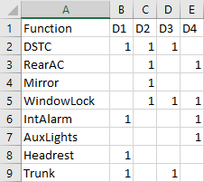
Anyone with basic soldering skills will be easily able to change the function of any button. Changing the symbol, not so easy 😉